top of page
Helicopter Turbine
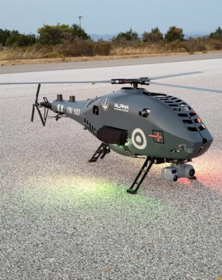
Over the summer of 2023 I worked in Spain with helicopter company Alpha Unmanned Systems where I did several projects. My final one was to design, manufacture, and test a pulley driven turbine fan to help cool the internal components of the aircraft to increase performance.
(Please note certain details of this project are left vague so as to comply with the company's NDA)

Design Process
Due to the nature of light aircraft, especially combustion powered helicopters, over-heating is a big concern. This is normally fixed using fans and other cooling implements. The A900 uses several such methods. Despite this the lower portion of the helicopter could gain performance with further cooling. Implementing cooling solutions in this space however is difficult due to the compact design of the helicopter. To get around this a possible solution was devised to turn the interior of one of the transmission pulleys into a fan. The chosen pully was directly coupled to the engine shaft and had the right orientation, unfortunately it also served a primary role in transmitting power to the main rotor blades necessitating a high level of strength and reliability.
To Start the original pulley was studied. It was measured and then precisely modeled in CAD. Its rotation and orientation within the helicopter was also recorded. From this model a maximum possible inner and outer diameter of the fan was found. Then using basic fan equations maximum air flow was calculated as a reference for tests. A model was then made simplifying the outer geometry. It was found that the maximum blade number using standard blade angles and the full depth of the pulley was 3. From there three blade designs where made using a basic aerofoil and three different blade pitches. These were made by drawing a lofted helical shape bounded by 6 3D points.

These designs were then 3D printed and tested. To test the models they were given a special mounting hole to allow them to be threaded onto an electric motor. This motor was then held in place with two iron beams and spun up to speed while the airflow exiting the fan was measured. From this the moderate blade pitch design was picked. This design used a low angle at the top to scoop the slow moving air and then rapidly pitched down towards the end to redirect air and accelerate it downwards. Considering the roughness of the test models and the maximum air flow the design did surprisingly well.

After these tests the design was modified to assure it could be attached properly to the shaft within the helicopter. It was also modified to limit weight and to make sure it could be made with the specified machining process of 3 axis CNC. After these modifications the new part was tested in simulation software for strength and aerodynamic performance. The part was then sent off to be reviewed by other design engineers and manufactured.


Final Pulley design (Top Right)
Pulley Structural analysis (Left)
Additional Work:
While at Alpha I completed several other projects. I first started by reviewing the training material and then taking the pilot and maintenance exams of both helicopter models. After that I went through to suggest improvements and create new course content to explain engineering and aeronautical concepts. I also helped to create new courses for various flying conditions as well as basic website maintenance. Following this work I preformed several tests and small tasks such as stress testing parts and working through payload compatibility problems. My final project before the turbine fan was to design and construct a new propellor testing rig. This is shown below.

bottom of page
